Essential System Testing for Long-Term Solar Project Performance
Comprehensive system testing is crucial for maximizing energy production and extending the operational life of solar systems.
Solar energy systems are designed to provide reliable energy production for decades, but hidden issues can silently reduce performance until small failures become large failures, costly repairs, and even safety issues.
For solar owners, developers, and operators, investing in comprehensive and proactive system testing is one of the most effective ways to maximize energy production and extend the operational life of any solar system. From construction and commissioning to ongoing operations and maintenance, proper system testing helps identify electrical faults, equipment degradation, installation issues, and performance concerns before they cause significant damage and revenue loss.
## Essential System Testing Practices
Various testing measures should be performed during construction, commissioning, and annually (or semiannually) as a proactive maintenance plan. The following essential system testing practices will make the difference between a system that performs long-term and one that faces challenges throughout the project lifespan.
### Thermal Imaging
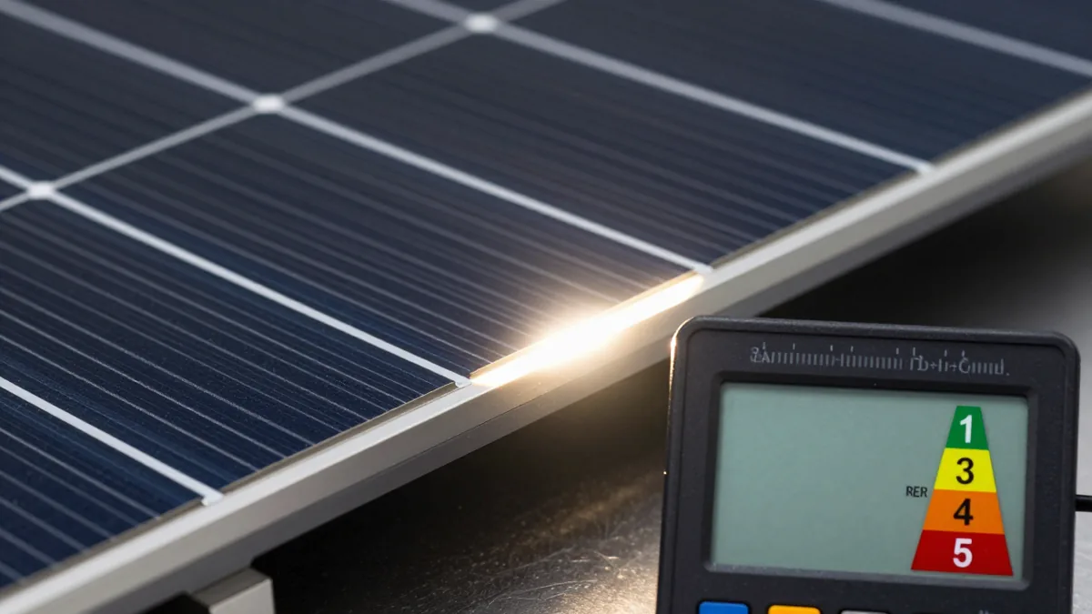
Thermal imaging detects temperature variations across modules, electrical components, and equipment, pinpointing various production and safety concerns not visible to the plain eye. By pinpointing heat anomalies, thermal imaging can often discover issues early on, allowing for correction before larger failures happen. Thermal imaging can detect:
| Issue | Description | | --- | --- | | Module hotspots | Temperature variations across modules | | Defective modules | Modules with electrical or mechanical issues | | Module soiling | Dirt or debris on modules reducing performance | | Array shading | Shading affecting module performance | | Failed bypass diodes | Faulty bypass diodes reducing module performance | | Loose electrical connections | Poor connections affecting electrical flow | | Offline strings and combiner boxes | Strings or combiner boxes not functioning correctly | | Offline Inverters | Inverters not functioning correctly |
Thermal imaging should be performed during commissioning, once a system has been energized. For maintenance, it should be performed annually as a baseline, with best practice being twice a year, before peak irradiance and before winter hits (spring and fall). If a system is facing ongoing production concerns, performing thermal imaging more often may be needed.
### IV Curve Tracing
IV curve tracing is an essential diagnostic test to determine the performance of modules and strings by recording the relationship between current (I) and voltage (V). That “curve’ can then be compared to module performance expectations. Unlike system monitoring, which can detect when a system is underperforming, IV curve tracing helps determine why underperformance is happening. IV curve testing can detect a wide range of problems, such as:
| Issue | Description | | --- | --- | | Degrading or aging modules | Modules with reduced performance due to age | | Damaged modules | Modules with electrical or mechanical issues | | Shading losses | Shading affecting module performance | | Soiling impacts | Dirt or debris on modules reducing performance | | Damaged connectors | Poor connections affecting electrical flow | | Open circuits | Electrical issues affecting module performance | | String wiring errors | Wiring issues affecting string performance |
IV curve tracing should be performed during commissioning to verify that newly installed modules and strings meet design specifications. For maintenance, annual testing is suggested to monitor system health and detect degradation over time. However, additional IV curve testing should be performed if production drops significantly or after severe weather events where modules may have been damaged.
### Insulation Resistance (Megger) Testing
Insulation resistance testing, also known as Megger testing, is an electrical diagnostic test used to verify the integrity of insulation on cables, equipment, and circuits. By measuring the resistance to current leakage, this helps identify weaknesses in insulation before they lead to equipment damage, ground faults, or safety hazards. Over time, insulating material can deteriorate due to moisture, UV exposure, heat, mechanical damage, and more.
Insulation resistance testing is performed during the mechanical completion stage of commissioning, before a site is energized to ensure a system is safe to operate. During preventative maintenance (annually), insulation resistance testing should be performed to monitor insulation health as a system begins to age. Other instances when IRT (insulation resistance testing) may be performed is during troubleshooting, especially if a ground fault is expected. As well as after repairs, such as cable or electrical repairs.
### DC String Testing
DC string testing is an essential electrical test that verifies each string of modules is operating correctly and is producing the expected electrical output. By testing individual strings, technicians can identify wiring errors, damaged modules, faulty connectors, or electrical issues. On a utility-scale solar site with thousands of strings, identifying even a small percentage of underperforming strings can recover a meaningful amount of lost energy production.
DC string testing is usually performed during commissioning before a site is fully energized, but after modules, wiring, combiner boxes, and associated DC equipment have been installed.
### Ground Continuity and Bonding Verification
Ground continuity and bonding verification is an essential test to confirm that all metallic components of the solar electrical system are properly connected to a grounding system, in the case that faults occur. Without proper grounding and bonding in place, a fault in the electrical system could energize metal equipment, resulting in electrical shock, equipment damage, or fire hazards.
Ground continuity testing is a standard commissioning task that should always be performed. However, it should also be performed during preventative maintenance checks, as grounding systems can degrade over time due to corrosion, loose connections, environmental exposure, etc. Ground continuity testing may also be performed if major repairs or equipment replacement has occurred, to ensure all repaired or new equipment has been properly connected to the grounding system.
### MV Equipment and Cable Testing
Medium-voltage equipment usually consists of pad-mounted transformers, switchgear, circuit breakers, reclosers, disconnect switches, collection cables, and more. All these components carry a large amount of electrical power and even a minor defect can have major consequences. Performing various testing measures such as VLF cable testing, insulation resistance testing, and more will verify the integrity of MV equipment.
A failure anywhere in the MV system can take a large section, or even an entire system offline, resulting in significant production losses, downtime, and costly repairs. Performing testing on MV equipment can reveal moisture intrusion, damaged cable insulation, poor cable splices, loose electrical connections, and protective relay issues. Most of these issues are hidden underground or inside electrical enclosures and require a series of testing measures, not just a visual inspection.
Various MV equipment and cable testing measures should be performed during commissioning to ensure equipment was installed correctly and is safe to operate. MV equipment maintenance should be top priority for every site and be included in yearly maintenance. Over time, all electrical systems can age and incur issues due to heat, moisture, electrical stress, mechanical movement, and environmental conditions. Additional MV testing should be performed if electrical faults, lightning incidents, or damage to cables occur.
### Ground Resistance (Fall of Potential) Testing
Ground resistance testing is commonly performed using a fall of potential method, which measures how effectively a solar site’s grounding system dissipates electrical current into the earth. Unlike ground continuity testing, which verifies that equipment is connected to the grounding system, Fall of Potential testing measures the effectiveness of the grounding system itself.
The test is performed using a specialized ground resistance tester and two temporary electrodes driven into the soil. The importance of an effective and safe grounding system is essential if ground faults, lightning strikes, short circuits, or electrical surges take place. If ground resistance is too high, equipment may remain energized during faults, resulting in significant damage, or protective devices not operating.
Fall of potential testing is most commonly performed during commissioning, to ensure a site’s grounding system meets the project’s design specification and electrical standards.