Terrain-adapted PV design essential for
Solargis CEO Marcel Suri argues that precise 3D terrain modeling is critical for bankable energy yield estimates in utility-scale PV projects built on
Complex site topography has a crucial bearing on a PV system's energy yield, according to Solargis CEO Marcel Suri. In a market with tight margins, precision in terrain-aware modeling is essential for smart engineering and risk management.
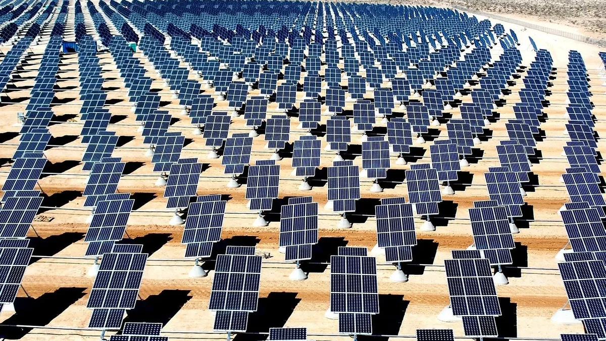
In photovoltaics, terrain is not a cosmetic detail. Many utility-scale projects are built on sloped, hilly, or irregular grounds. These variables must be accounted for.
Complex topography affects PV performance in two fundamental ways. Optically, it changes shading behaviour and view factors. Electrically, it affects operating points and losses dependent on irradiance variability, temperature, and angle of incidence. If the simulation geometry does not match the design geometry, the introduced uncertainty is systematic. Wrong geometry leads to wrong yield estimates.
This is why PV layouts should reflect real terrain. The goal is to reduce construction risk and avoid inaccuracies. In practice, however, the connection between design and simulation is often weak.
Designers may import a detailed 3D terrain model, but many software solutions simplify it. They smooth out slopes and remove local variations, treating the entire plant as if built on flat ground. The terrain data is lost.
Getting terrain data into the design workflow
The first challenge is obtaining and importing accurate terrain data into a PV design tool that supports terrain-adapted design.
The industry uses a wide range of terrain sources. Many tools rely on global Digital Elevation Model (DEM) layers with 30-90-metre resolution. This data can be years or decades old. It is adequate for early screening but can be misleading in mountainous terrain, valleys, on terraced land, or on sites shaped by earthworks.
For detailed design, importing custom terrain is typically needed. The GeoTIFF format is often the most robust because it carries georeferencing information in the file header. Multiple tiles can align correctly without manual stitching.
A key point is that 'terrain' data is not always pure terrain. Remote sensing products like LiDAR may include tree canopies, buildings, or temporary structures. This can be useful for capturing near shading without manually modelling every obstacle.
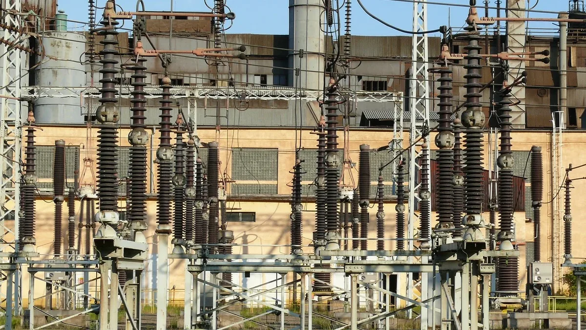
It can also be a problem. Artefacts like power lines can be reconstructed as solid walls rather than cables, producing unrealistic shading and false collisions. Terrain data needs scrutiny before it becomes design truth.
Making high-resolution terrain usable
Even with good terrain data, computational constraints exist. A detailed LiDAR or drone scan produces a large 'point cloud' of many gigabytes. Manipulating these raw datasets interactively in a browser-based environment is often unrealistic.
A useful approach is to convert elevation data into an optimised triangular mesh. This preserves important ridgelines and slope breaks while reducing triangles in nearly flat areas. Algorithms like Mapbox's 'Delatin' accept a controlled loss in geometric fidelity for a mesh that can be rendered and edited smoothly. The goal is maximum relevance where design decisions are sensitive to slope and shading.
The marriage of physics and constructability
Once terrain is usable, a central question remains. Does the PV layout conform to it, and does the simulator honour that same geometry?
On undulating ground, table placement changes continuously. Row-to-row clearance, pile heights, and tracker rotations interact with slope and local curvature. In tracker systems, a table that clears the terrain at one rotation angle may intersect it at another. Checking geometry only at a neutral position can miss collisions during morning or afternoon tracking.
A terrain-adapted layout needs two qualities. It must place structures on the terrain with realistic constraints. It must also preserve the detailed geometry into the simulation step where shading and irradiance distribution are computed. If the simulator uses a flattened approximation, the point of terrain-aware design is lost.
On complex terrain, collisions are not rare. They are a predictable consequence of steep slopes, short clearances, and non-uniform table heights. Collisions can occur between adjacent tables in a deep valley, between tables and the terrain, and between tables and equipment like inverters.
Smart collision detection prevents late-stage redesign. It reduces the risk of constructability problems arising after procurement decisions are made. Robust software detects collisions immediately as the designer edits the layout.
Accounting for slope direction
Most engineers know slope limits. A surface can be too steep for economical construction. But slope magnitude alone does not describe terrain suitability.
In the northern hemisphere, a given slope angle has different implications depending on whether it faces south or north. The same grade can support favourable module orientation or create persistent shading and access problems.
Terrain azimuth, the directional orientation of slopes, should be a first-order design variable. The best terrain-aware decisions combine slope magnitude, slope direction, and local shading context into a single constraint view.
Snow, soiling, and bankable yield
Terrain changes the effective tilt and exposure of PV surfaces. This influences soiling dynamics and snow behaviour. In mountainous regions, differences in surface tilt and local wind patterns affect how quickly modules shed snow and how rainfall cleans surfaces.
A model cannot 'solve' snow and soiling perfectly. But ignoring terrain in the geometry can lead to applying loss assumptions inconsistent with how the plant will actually behave. For banks and investors, these inconsistencies show up later as performance surprises.
For projects in complex topography, a straightforward question for any simulation provider is crucial. How does your engine represent undulating terrain in the actual yield calculation? Does it use the same 3D geometry you designed, or a flattened layout?
Terrain-adapted PV design ensures the geometry you model is the geometry you simulate. The physics of the site must be preserved all the way into bankable energy yield assumptions. When simulation is done at the cell level on a realistic terrain model, the loss breakdown becomes more honest. You can see which energy losses are driven by topography, weather conditions, and which by design choices like row spacing or tracker geometry.